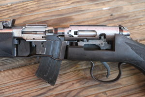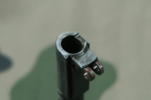


Today, we are gathering around a Winchester 94 rifle. This weapon is very well known and equally widespread. It has been manufactured in large numbers and is part of a certain landscape. However, some information remains poorly documented. For example: how is the barrel assembled onto the receiver? How do you remove the barrel from a Winchester 94? How do you install a barrel? If it is screwed in, what is the tightening torque ? Is the barrel glued, pinned ? …
What method is used to assemble the barrel onto the receiver
-
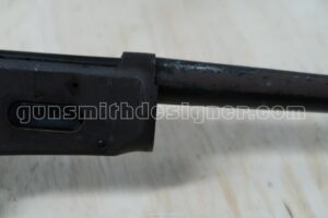
- Winchester 94, the barrel is mounted on the receiver.
-
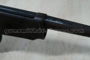
- Winchester 94, the barrel is screwed onto the receiver.
As stated above, it is possible to secure the barrel to a weapon’s receiver (or receiver block) in several ways (screwed, pressed/fretted, pinned, welded barrel…). It is not always obvious to determine which method was chosen once the firearm is assembled. You will find a set of photos below, and I will let you discover the method used to link the barrel and the receiver.
-
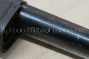
- Winchester 94, barrel / receiver assembly.
-
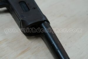
- Winchester 94, receiver / barrel assembly.
Regarding the barrel of the firearm that brings us together today, it is screwed onto the receiver block. The thread direction is standard: right-hand (clockwise) to tighten / left-hand (counter-clockwise) to loosen. The base diameter of the thread is: 20.5 mm. The thread pitch is: 20 threads per inch. There are no traces of thread locker, no pins, and no retaining screws. The tightening torque alone ensures it stays in place. This information was obtained after disassembly.
-
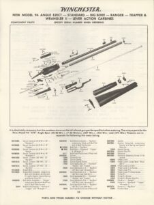
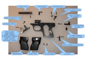
- Exploded view of the Winchester 94.
-

- Exploded diagram of the Winchester 94.
-

- Exploded view of the Winchester 94.
Due to a lack of access to the manufacturer’s production standards, it would be interesting to disassemble various Winchester rifles to determine statistical data and answer the following questions: are the diameter and pitch identical for a firearm of a different caliber? At what caliber or on which models do the thread dimensions or torque change ?
Before any manipulation on a firearm, ensure that it is unloaded and respect the safety rules.
What tooling?
The main qualities of this tooling must be :
- Not to damage the barrel ;
- Not to distort the receiver ;
- To protect the original bluing of the parts ;
- To have a rigid fixture adapted to the barrel of the firearm, clamped without play on a support that does not move either ;
- To have a rigid fixture adapted to the receiver or receiver block, secured without play onto it ;
- A torque wrench (if you wish to quantify the torque);
- A lever arm to multiply the force (if necessary).
The equipment for the disassembly of the Winchester 94 :
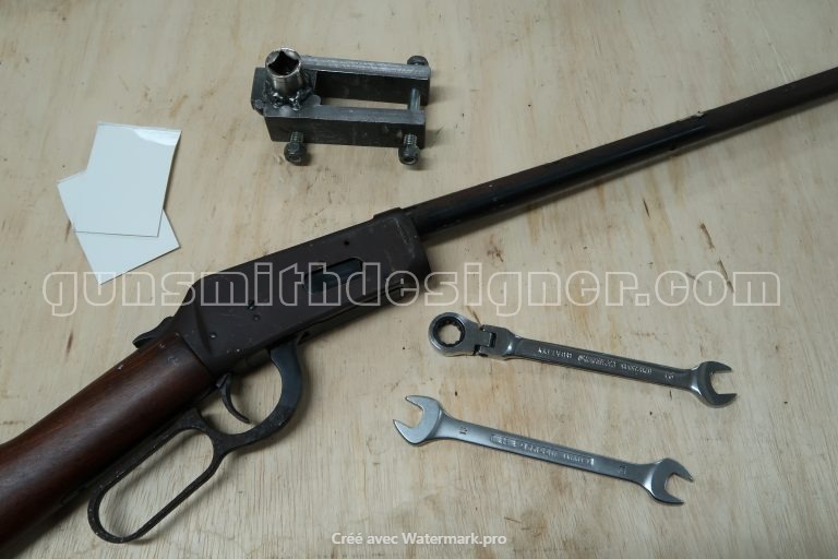
• Winchester 94 and some of the tools before disassembly.
- The fixture on the receiver block side is designed to hold the components securely. Proper alignment relative to the barrel axis is necessary to monitor the forces applied during the process;
-
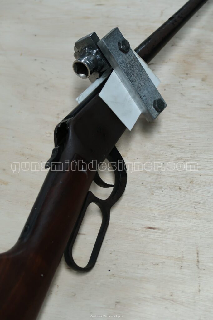
- Winchester 94, barrel removal.
-
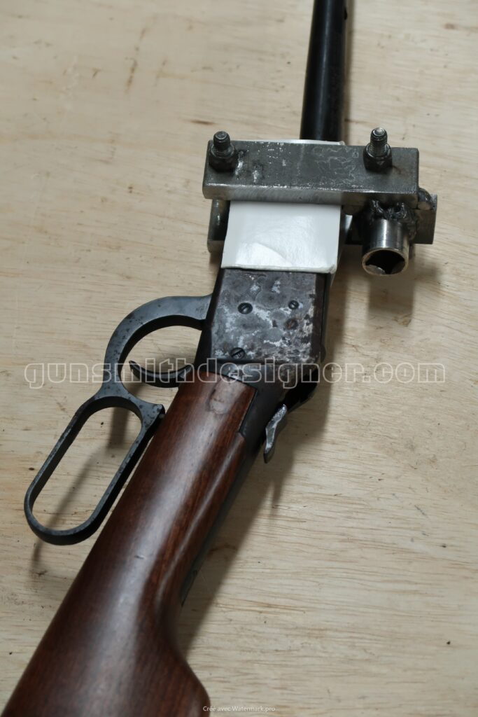
- Winchester 94, barrel removal.
- The fixture on the barrel side utilizes a secure clamping mechanism. High rigidity in the supporting equipment is a critical factor for safety and precision. Specialized jaws are employed to ensure a secure fit without slippage against the barrel profiles;
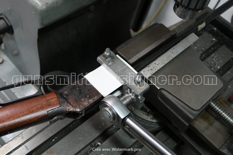
Winchester 94, the barrel is held firmly before disassembly.
- The force measuring equipment. Professional grade instrumentation with an appropriate measurement range is utilized to quantify the mechanical force required;
-
- Wurth torque wrench
-

- Wurth torque wrench 60 to 300 N.m.
-
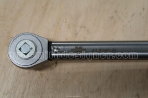
- Wurth torque wrench
Deciding whether to secure the barrel or the receiver depends entirely on the specific workshop capabilities and resources available.
On the Winchester 94, specific attention must be paid to the position of the internal components, such as the bolt and extractor, before attempting any separation. If the internal mechanisms are fully locked, the extractor remains engaged within its slot in the barrel. Attempting separation under these conditions can cause severe mechanical damage to the extractor, the bolt, or the barrel breech. Proper positioning of the action is required to avoid component interference.
Determining the torque during barrel removal.
Quantifying the assembly forces requires systematic measurement. The components are secured in specialized rigid supports, and measurement interfaces are attached to monitor the torque required to overcome the original factory fit.
The application of force is monitored progressively. Initial assessments begin at lower parameters to verify the setup stability and avoid sudden component stress. Force is increased incrementally until the mechanical resistance is overcome, allowing the components to separate smoothly.
View of the torque wrench dial: 120 Nm.
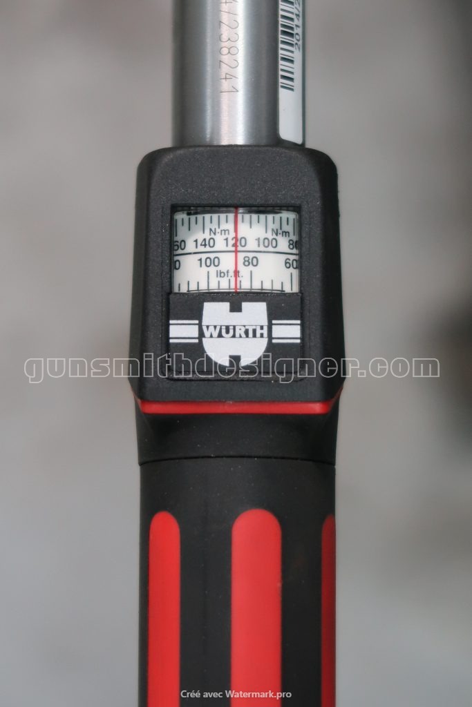
View of the torque wrench dial: 120 Nm.
- Inspect the components for structural integrity;
- Check for any burrs or manufacturing irregularities;
- Ensure the complete absence of foreign objects or debris;
- Verify that male and female threads are completely undamaged;
- Check the overall condition of the receiver block for stress signs or deformation;
- Verify the internal condition of the chamber and the barrel bore.
Below are a few photos of the removed barrel.
-
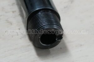
- Vue de la face arrière d’un canon de Winchester 1894.
-
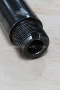
- View of the extractor slot, Winchester 94.
-
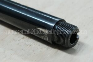
- View of the underside of a Winchester 1894 barrel. Presence of a flat.
If the bolt is closed during loosening
The following documentation demonstrates the mechanical consequences when internal components are improperly positioned during separation.
The photos below show the resulting deformation of the extractor slot area.
-
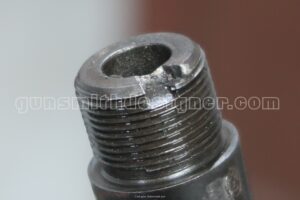
- Winchester 94, close-up of the extractor slot.
-
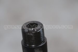
- Winchester 94, close-up of the extractor slot.
-
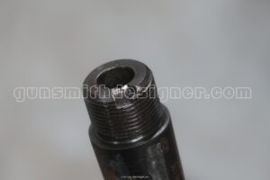
- Winchester 94, close-up of the extractor slot.
-
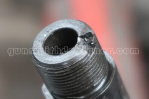
- Winchester 94, close-up of the extractor slot.
Any deformation or burring caused by improper component alignment can negatively affect the mating threads of the receiver block during disassembly. The photos below illustrate the potential resulting damage to the interface threads.
-
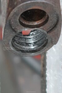
- Winchester 94, the barrel thread.
-
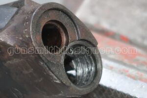
- Winchester 94, the front face of the receiver.
-
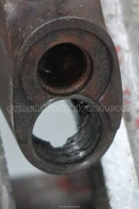
- Winchester 94, the front face of the receiver.
Reinstalling the barrel
Following complete inspection and cleaning, alignment verification is performed. Component engagement must be smooth; any binding or resistance indicates a need to halt the process and re-examine the threads.
Reassembly follows standard engineering principles in reverse sequence :
- Verify initial thread engagement manually;
- Stop immediately if any resistance or hard spots are encountered;
- Align the components properly within the specialized holding fixtures;
- Utilize protective materials between the tool surfaces and the finished surfaces to preserve the original bluing;
- Apply the appropriate tightening force in accordance with established technical specifications;
- Ensure final torque aligns with the recommended standards for secure assembly;
Verification of component indexing is necessary to ensure that the extractor slot aligns perfectly with the extractor mechanism and that the sighting components maintain correct orientation relative to the receiver frame.
Analyzing these procedures allows for the determination of manufacturing specifications, such as assembly torque, and highlights the importance of specialized tooling in preserving the condition of historic or modern firearms during maintenance.
Further study across a broader sample size would be beneficial to compile comprehensive technical data regarding different calibers and production eras.
The data presented reflects observations from a single specimen. Because manufacturing techniques and standards change over time, variations are expected. Professional gunsmithing work requires specialized training and adherence to strict safety standards. For complex modifications or maintenance, consultation with a certified professional is recommended.
Respect the safety rules!!!
For technical analysis and statistical documentation regarding the maintenance of these models, feel free to contact the author.