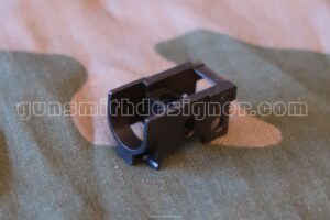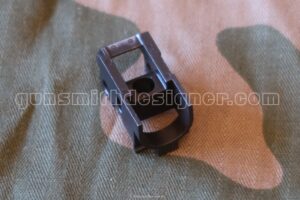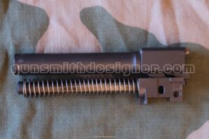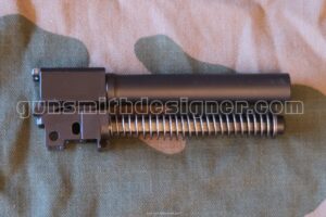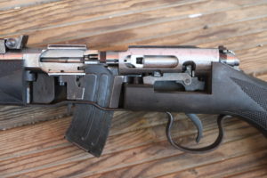
The Squire Bingham 12-Gauge Pump-Action Shotgun

The Squire Bingham pump-action shotgun is one of the few shotguns of this type to feature a barrel screwed into the receiver. Throughout this article, we will cover the following points:

    • Overview of the parts: receiver, barrel, bolt, magazine tube.
    • The manufacturer made the barrel and the receiver a single permanent unit. Is it necessary to remove the barrel? If so, why and how should it be done? How do you reinstall the barrel after removal?
    • How is the receiver of the Squire Bingham pump-action shotgun machined? Why is the bolt locking recess located in the receiver?

Overview of the parts

The receiver

The receiver of the Squire Bingham pump-action shotgun is made of steel. It is a heavy part, weighing: 858 grams.

It fits within a bounding box measuring: 188.5 mm x 63.1 mm x 34.6 mm.

For comparison, here are the bounding box dimensions of a Remington 870 receiver: 199 mm x 59 mm x 34.1 mm.

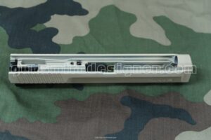
The stripped receiver, right side.

The stripped receiver, left side.

Inside the receiver:

Bottom view of the stripped receiver.

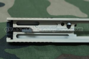
Right-side guide rails.

Left-side guide rails.

Top view of the receiver.

The two models disassembled for writing this article are different. I did not notice it at first glance, but one has a single action bar while the other has two. This can be seen in the photo below.

View of the front faces of two Squire Bingham pump-action shotgun receivers.

Front faces of two Squire Bingham pump-action shotgun receivers.

During the analysis of the firearm, I noticed that the rear of the receiver is a separate attached piece. One detail tipped me off: the sharp-cornered internal machining inside the receiver. This type of machining can only be achieved using specialized manufacturing methods, yet I doubt those would be applied to a low-cost shotgun from this brand. On the rear face of the receiver, rectangular weld marks are visible. I would say it is silver brazing or a similar process.

Rear face of a Squire Bingham pump-action shotgun receiver.

Below you will find photos of the rear of the receiver with and without the attached piece. Being able to make this comparison is a great opportunity, as these are not commonly seen views.

On the Remington 870, the manufacturer did not make this choice. The receiver is made from a single piece. It would be interesting to create a synthesis (physical or digital) between the Squire Bingham and the 870—namely, a pump-action shotgun featuring a one-piece steel receiver and a fixed barrel. There would likely be pros and cons. To be seen… that is another topic.

Rear face of the Squire Bingham pump-action shotgun receiver.

Rear plug of the Squire Bingham pump-action shotgun receiver.

Rear face of the Squire Bingham pump-action shotgun receiver.

Rear face of the Squire Bingham pump-action shotgun receiver.

The bolt locking recess is machined directly into the receiver. This could be an issue if the barrel were removable by the user. One would then have to ensure the part was properly fitted so that headspace remained within tolerances. Here, the problem is solved by having the barrel permanently secured to the receiver.

The bolt

The bolt and the locking block are a single piece. The locking block is the small angled projection located at the rear, on top of the bolt. At the end of its forward travel, the rear of the bolt tilts upward and engages its recess (in the receiver).

The bolt of the Squire Bingham pump-action shotgun.

Right side of the bolt.

The barrel

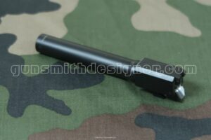
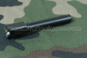
The steel barrel is cylindrical. It has neither a bolt locking recess nor an attached barrel ring connecting it to the magazine tube. It is simply screwed into the receiver (no threadlocker, no pin, no set screw).

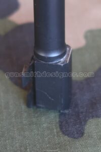
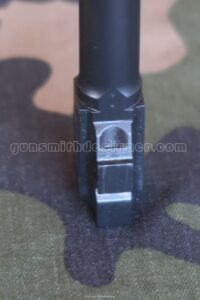
View of the rear face of the Squire Bingham pump-action shotgun barrel.

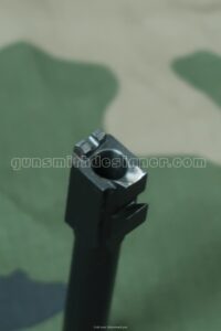
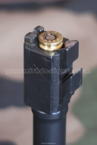
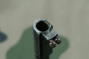
Chamber mouth of the barrel.

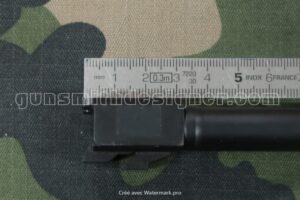
The outer diameter at the chamber is: 30.5 mm. CIP standards specify a minimum chamber diameter for 12 gauge of: 20.65 mm / 20.30 mm. This results in a wall thickness of approximately: 5 mm.

Markings on the stripped barrel.

Markings on the stripped barrel.

There is a flat machined along the bottom generatrix of the barrel. This is very useful, as it will allow us to firmly clamp the barrel to a rigid fixture during disassembly.

The thread diameter is: 27.8 mm.

The thread pitch is: 24 threads per inch (TPI), or 1.058 mm.

The length of the threaded shoulder is: 16.8 mm.

Photo of the barrel threads on a Squire Bingham pump-action shotgun.

Close-up of the barrel threads.

The magazine tube

The magazine tube is screwed into the receiver. To remove the forend, the magazine tube must be unscrewed from the receiver. This is due to the presence of a retaining collar and a spring on the exterior body of the magazine tube. These prevent the forend from being removed from the front. It must slide off the rear of the magazine tube, so if you want to clean your firearm properly from time to time, you have to remove the magazine tube.

View of the magazine tube parts that prevent front removal of the forend on the Squire Bingham pump-action shotgun.

The magazine tube, its collar, and its spring.

Four holes at the front of the magazine tube (two of which are used for the magazine cap screws) can be used for this purpose. This is easily done with little effort using a pin punch or a screwdriver. The tube is not glued to the receiver.

When buying a used firearm or during periodic maintenance, detaching, cleaning, and greasing it certainly cannot hurt.

Barrel removal

User-level disassembly does not include removing the barrel. This is a deliberate choice by the manufacturer. Why should we go beyond the manufacturer’s intent? If the firearm is new, very well maintained, or still under warranty, I believe it is inadvisable to separate the two parts. On the other hand, if the firearm requires a deep overhaul—such as re-bluing, heavy rust removal, bore polishing, sandblasting, or reaming the chamber to magnum—then removing it becomes necessary.

Receiver and barrel before disassembly, right side.

Receiver and barrel before disassembly, left side.

To avoid damaging any parts and to clear the necessary workspace prior to barrel removal, remove the unnecessary components:

    • The buttstock;
    • The magazine tube/barrel clamp;
    • The magazine tube cap (held by two screws);
    • The trigger guard assembly;
    • The bolt;
    • The magazine tube;
    • The forend.

Required tools:

    • The receiver fixture (receiver side);
    • A rigid clamping block (barrel side);
    • A torque wrench.

The fixture mounted on the receiver:

View of the receiver / barrel assembly ready for disassembly.

The receiver / barrel assembly mounted in its rigid fixture ready to be disassembled.

The method:

The first barrel broke loose at 220 N·m. On the second one, a torque below 190 N·m was sufficient.

Barrel installation

Index mark on the front face of the receiver.

We will use two witness marks present on the firearm that were made specifically for this purpose. The first is on the receiver, and the second is on the barrel. As you may have guessed, using the tools mentioned above, you must align both marks.

Index mark on the barrel.

Index marks after reinstalling the original barrel.

Before torquing, preparatory work must be carried out (cleaning the parts, removing burrs, greasing the threads, hand-tightening until it bottoms out against the receiver, inspection…).

Conclusion

Disassembly and reassembly are straightforward. There is no reason to hold back from giving firearms in need a proper rejuvenation. If you do not wish to do it yourself, have it done by a professional.

The locking recess is carried by the receiver. This is made possible because the barrel is not user-removable. Otherwise, headspace would have to be checked to stay within the tolerances defined by CIP standards, or the locking recess would have to be integrated into the barrel, as is the case on many pump-action or semi-automatic shotguns.

The trigger group is conventional. I chose not to cover that topic here. I may have the opportunity to do so at a later time.

The Squire Bingham pump-action shotgun is a heavy-duty, rugged firearm. It is built to last, provided it is properly maintained and refurbished when necessary.

A technician must look for engineering details in everything and at all times. Even if you do not own a Squire Bingham pump-action shotgun, I hope this article has sparked your curiosity.

If you like Gunsmith designer articles,

spread the word,

share this article.

Posted in Rifles | Leave a comment

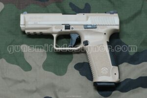
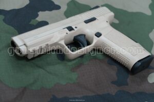
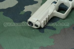
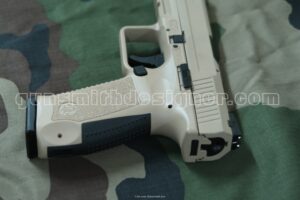
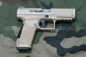
The CANIK TP9 SF pistol

The CANIK pistol seems to have a good number of fans and favorable reviews. Most reports about it look alike. What is hidden beneath its attractive aesthetics? What does a CANIK TP9 SF pistol look like on the inside ?

Presentation of the Firearm

Firearm specifications:

    • Caliber: 9×19;
    • Overall length: 230 mm;
    • Height (with magazine): 147 mm;
    • Height (without magazine): 138 mm;
    • Width: 33.5 mm;
    • Weight (with empty magazine): 809 grams;
    • Magazine capacity: 18 rounds;
    • Materials: polymer, steel;
    • Locked-breech firearm.
    • Link to the Canikarms website: TP9 SF
    • Link to the user manual

The Frame

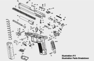
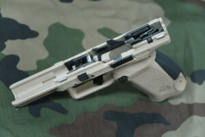
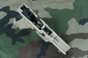
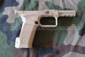
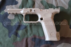
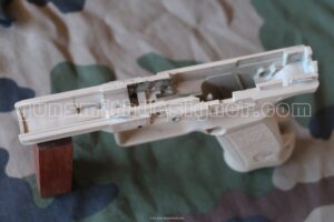
The frame houses the following sub-assemblies:

    • The trigger / trigger bar;
    • The locking block;
    • The takedown lever;
    • The slide stop;
    • The magazine catch;
    • The rear housing block;
    • The backstrap.

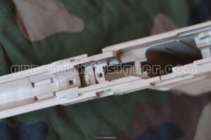
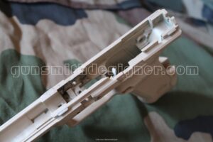
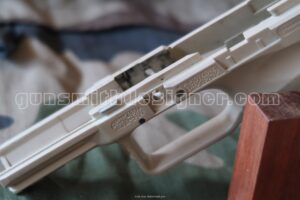
The stripped frame (stripped of all these components) weighs: 104 grams. Material: polymer with 4 steel guide rails.

To date, I am unable to determine the exact type of polymer used.

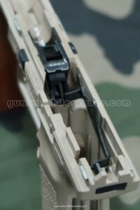
It is a nicely manufactured part. In the following photos, you can see the locations of the sub-assemblies on the frame.

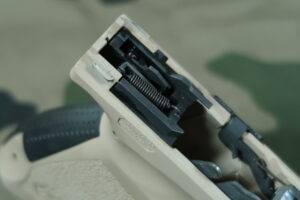
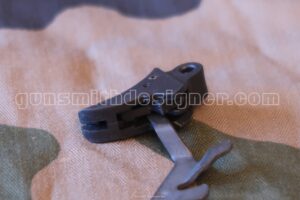
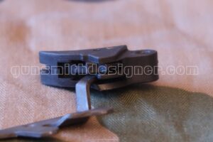
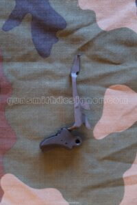
The trigger is made of polymer. In its center, there is a small safety lever. When the shooter pulls the trigger, it disengages the safety. The trigger bar is standard; it is a steel part pinned to the trigger. The trigger return spring connects the trigger bar to the trigger housing at the rear of the grip.

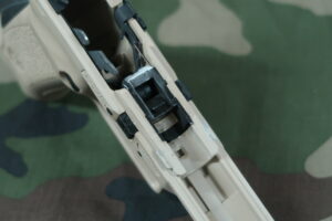
Removing this assembly from the frame is complicated. To do so, you must first remove the takedown lever and then the locking block.

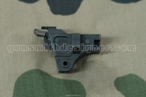
The locking block is a steel part produced by investment casting. This component controls the locking and unlocking of the barrel when cycling the slide. It is a major part of the firearm, absorbing significant shock and vibration. On Glock pistols, this part is known to crack. It is very likely the same on this firearm as well. Slide recoil velocity, recoil spring wear, and ammunition loads are directly linked to this effect.

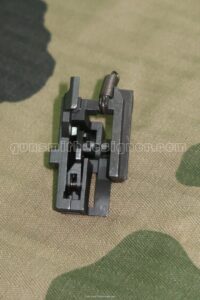
Photo du canon en position haute sur le bloc support de canon.To remove this part, the takedown lever must first be removed. This is not straightforward, as we will see later. The locking block is held in its housing by two pins, one of which serves as the pivot pin for the trigger and the slide stop.
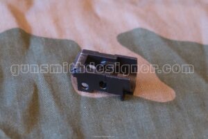
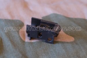
Some walls of the part seem thin to me. How many rounds would it withstand before cracking? A torture test could give us insights on this matter. I am not in a position to conduct such tests at this time.

To separate the slide/barrel assembly from the frame, you must pull down the takedown lever. This operates via a small transverse cross-pin that retains the barrel. Moving it out of the way frees the barrel, and freeing the barrel allows the slide to be removed.

This sub-assembly is particularly difficult to extract from the frame. I think it could have benefited from a better design; a pin of about 1.5 mm is very hard to drive out of its housing. With every hammer blow, the takedown lever spring absorbs the impact of the punch.

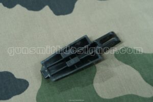
The magazine catch is a steel rectangle. It is an investment-cast part. Its spring is made of a good-diameter steel wire. The magazine catch is ambidextrous. If you wish to switch the button to the other side, you must remove the magazine catch spring from the top of the magazine well to reverse the catch. It is great to offer this feature to customers, but on the CANIK TP9 SF, putting the spring back in place after switching sides is not easy.

The slide stop is made of stamped sheet steel. Although complex, this part is very well made. The trigger pin also acts as the slide stop pivot pin. Its spring is held in place between the polymer frame and the locking block. To remove the spring from its housing, you must first remove the locking block.

The backstrap is made of polymer. It is removable and interchangeable, held in place by a roll pin. Depending on the shooter’s hand size, the grip volume can be adjusted. For several years now, this feature has become very common.

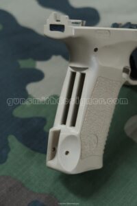
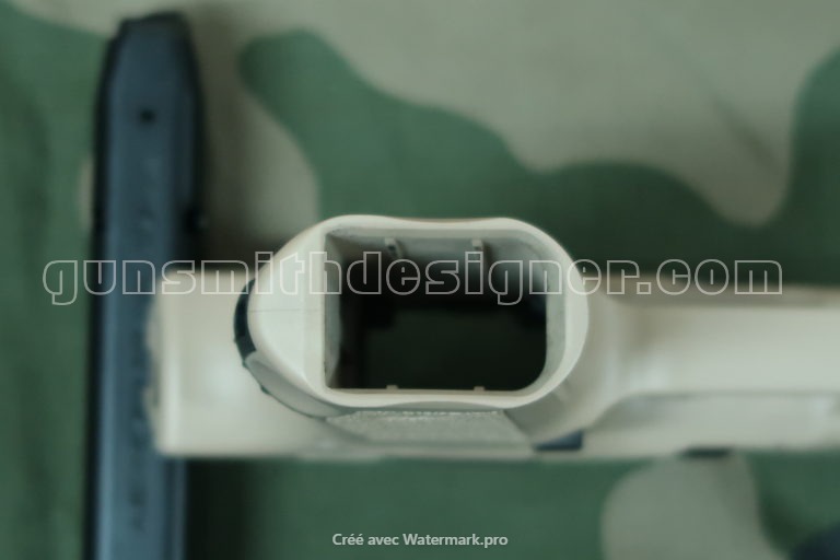
The magazine well features two raised ribs on each side, right and left, to reduce friction and limit the effects of dirt or debris.

Photo of the magazine well in the frame.

The Trigger Mecanism

The trigger housing is a massive steel block. The ejector is integrated into the block. It is an investment-cast part; it would be impossible to manufacture this piece by milling. It contains:

    • The sear and its spring;
    • The sear lever and its spring;
    • The trigger return spring.

Photo of the top of the trigger housing.

It is held onto the frame by a pin.

The sear is an investment-cast part. This is the component that catches and holds the firing pin (striker) when the slide returns forward.

The sear lever is an investment-cast part. This component prevents the sear from dropping. When the shooter pulls the trigger, the trigger bar acts upon this part to release the sear.

The trigger return spring is connected at one end to the trigger housing and at the other to the rear of the trigger bar.

The Barrel

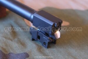
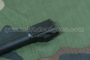
The barrel is made of steel. Its overall length is 113.6 mm. It has a classic shape for a 9mm semi-automatic pistol barrel. It uses a Browning/Colt linkless locking system with camming lugs. The locking surface appears to have less area than on a Glock (particularly in height).

It fits within a bounding box of 113.6 mm x 15.54 mm x 22.4 mm.

The length of the rectangular breech block is:

The cylindrical section has an outer diameter of 14 mm.
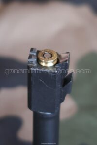
CIP standards specify the following minimum bore dimensions for this caliber:

    • Land diameter: 8.82 mm;
    • Groove diameter: 9.02 mm;
    • Rifling twist rate: According to the manufacturer: 1 turn in 16 inches (406 mm); according to CIP standards: 250 mm;
    • Number of grooves: 6 grooves, left-hand twist.

The feed ramp is very clean and appears to be chrome-plated, as does the bore.

Barrel Locking

The swinging link(s) of the Colt-style locking system have been replaced by inclined camming surfaces. The principle remains the same. Depending on the position of the barrel relative to a reference surface, it sits in the upper position (locked) or lower position (unlocked). In the photos below, you can see the position of the barrel relative to the reference surface, which is the locking block.

The Slide

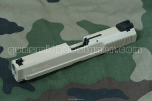
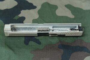
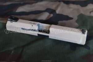
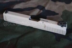
The slide is a massive, very well-machined steel part. It fits within a bounding box of 191 mm x 28 mm x 33.8 mm. Its stripped weight (including rear and front sights) is 352 grams.

Markings:

    • On the right side: TP9SF, CENTURY ARMS INC GEORGIA, VT
    • On the left side: CANIK, 9×19

A sand-colored (FDE) finish coats this part. It does not appear to be very durable.

The slide is guided by the 4 small steel inserts in the frame (two on each side). The dimensions of the slide rail grooves are 1.7 mm high by 25.2 mm wide (edge to edge).

Overall, disassembling the slide is a real pleasure and allows for quick stripping with very few tools. I did not attempt to remove the sights.

Slide travel (from its forward stop to its rear stop): 37.5 mm.

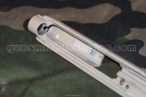
The stripped slide

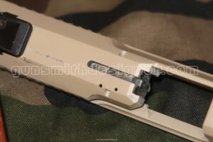
The loaded chamber indicator is a small piece located on top of the slide. Its pivot pin has a diameter of 2 mm and is a spring roll pin (rolled steel sheet). When raised by the presence of a chambered round, it reveals a small red dot on each side.

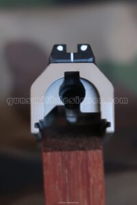
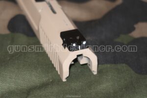
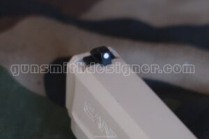
The sights are removable and dovetail-mounted. The front sight measures 3.8 mm wide.

The guide rod and its recoil spring form a single captive assembly. The guide rod is made of steel with a solid diameter and has a noticeable weight.

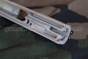
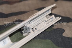
The extractor housing is complex; I hope the photos convey this complexity.


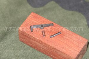
The extractor is an investment-cast steel part, measuring 4.92 mm wide. One interesting feature of this firearm is the extractor pivot pin. Indeed, there is no need to punch out a pin to remove the extractor and clean its channel. The pin is actually a spring-loaded plunger. To remove the extractor, you simply push this plunger/pin down into the slide. Once depressed far enough, the extractor can be lifted out.

The firearm is equipped with a firing pin safety. It is an investment-cast steel part that acts on the front end of the firing pin (striker), which explains the latter’s shape.

The firing mechanism looks very similar to that of a Glock pistol.

Photo of the firing pin assembly.

The firing pin sleeve is made of steel. It measures 33.6 mm long, with a bore diameter of 9 mm. I believe it is an investment-cast part (though not obvious) because a very slight “orange peel” texture is visible on the inside. On a Glock, this sleeve is made of polymer.

The firing pin (striker) is an investment-cast steel part, measuring 65.4 mm in length.

The firing pin spring has a diameter of 6.8 mm, a free length of 71.5 mm, and a wire diameter of 0.7 mm.

The firing pin spring.

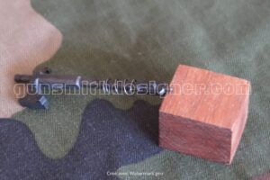
The firing pin return spring has a diameter of 6 mm, a free length of 11 mm, and a wire diameter of 0.4 mm. The Glock does not have a firing pin return spring. In the photo below, this spring is mounted around the firing pin.
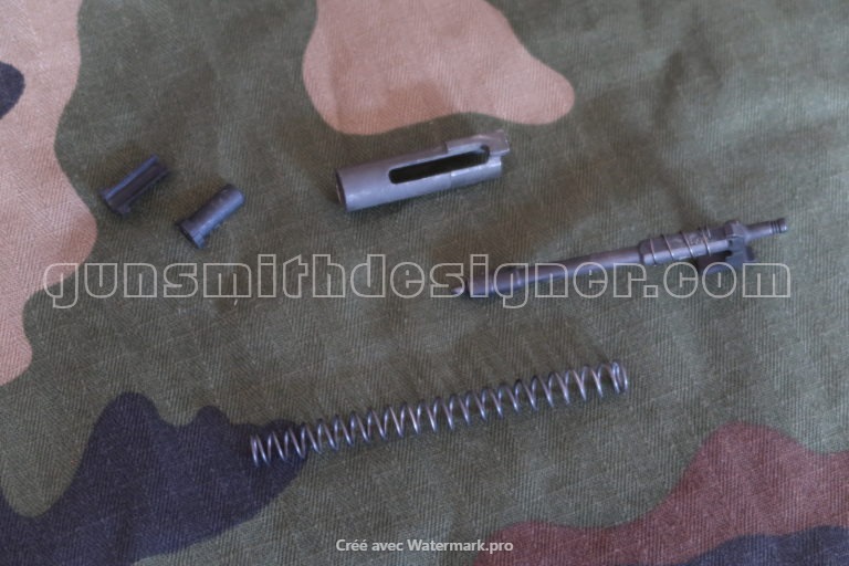
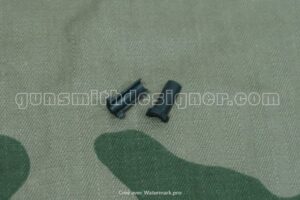
Two small polymer half-cylinders (spring cups), 13.6 mm long, hold the assembly in place on the firing pin sleeve. Outer diameter: 5 mm; inner diameter: 3.7 mm.
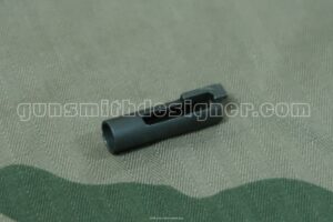
Photo of the two firing pin spring cups.

The slide cover plate is made of polymer with a steel insert. This part is very easy to remove, which is not the case on a Glock pistol.

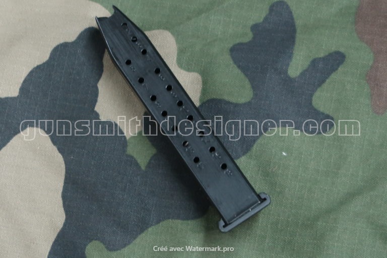
The Magazine

Specifications :

    • Magazine dimensions: 122.2 mm x 41.5 mm x 28.4 mm;
    • Magazine body cross-section: 32 mm x 20.5 mm;
    • Magazine height: 122.2 mm;
    • Magazine capacity: 18 rounds;
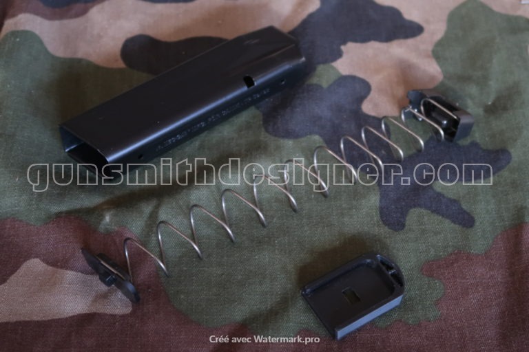
    • Number of parts: 5.

Photo of the rear of the magazine.The magazine is manufactured by MEC-GAR. It is very well finished. The body is made of steel, while the follower, locking plate, and floor plate are made of polymer. It disassembles very easily.

• Photo of the disassembled magazine.

Conclusion

Beneath modern and robust appearances, we discover a firing mechanism that is not derived from Glock, but rather from the MAB or Browning 1910… It seems difficult to find truly innovative mechanisms, even on firearms that look modern.

As we have seen above, many parts are manufactured using the investment casting process. It will be interesting to see over time how these numerous small-volume cast components hold up, particularly the locking block.

While disassembly is easy for the slide and its sub-assemblies, I am disappointed by the removal process of the takedown lever. This can cause issues if one wishes to replace certain accessories.

Posted in Handguns | Leave a comment

Simplification Through Division and the Jager Pistol

As we have seen in previous articles on the Charter Arms Undercover revolver and the AMT Backup II pistol, some designers use the principle of simplification through division to create a product.

AMT uses simplification by division on the slide of the Backup II pistol (the slide of this firearm is made of several pieces), whereas Charter Arms applies it to the frame of its revolver (the frame is made of several pieces). This raises a few questions :

  • Is it possible to generalize this process to all major components ?
  • Does a firearm exist that incorporates this principle across a large portion of its parts, and especially its major components ?
  • Is there a company that saturates one of its products with this principle.

The Jäger Pistol

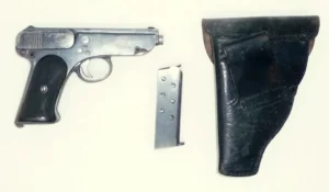
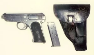
While browsing the internet, I found the answer to my question at the following address: The Jägerpistol – German 1914 : the Jäger pistol. The site discusses the history of this firearm, which I will not cover here since I am only interested in the technical aspect. Nevertheless, it seems that 13,000 of these firearms were manufactured.

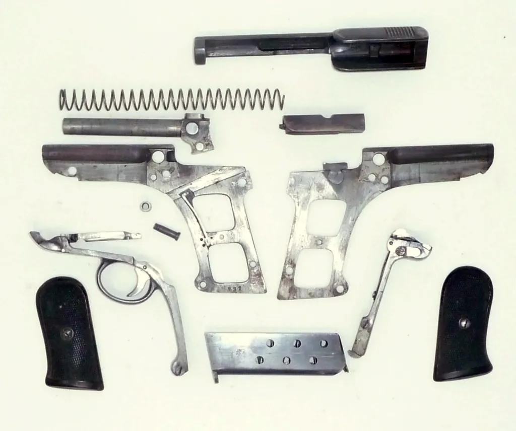
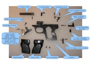
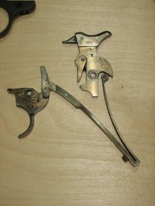
Here are the photos of the Jäger pistol featured on that site :

The disassembled firearm perfectly illustrates this principle of simplification by division.

As you can see for yourself, simplification by division has heavily defined this firearm. One could almost say that it was used to excess on this model. In place of a traditional frame, this pistol has two side plates: a right one and a left one… I won’t say any more, the photos speak for themselves.
Note that the caliber (probably 7.65 Browning / .32 ACP) does not require a locked breech. This makes it possible to further simplify and lighten the mechanism.

Conclusion

Even today, this design is not widespread. What would be the value of such a firearm today?

Could we ever see a modern Jäger reappear? How many rounds can it withstand ?

Perhaps the future will allow me to get my hands on one of these firearms and photograph it from every angle.

Posted in Handguns, Manufacturing techniques | Leave a comment