

In 1934, a replacement for the P08—deemed temperamental, difficult to manufacture, and somewhat outdated in design—was sought.
A prototype created in 1936 by the Walther company was modified in 1937 to be submitted for German military trials. On the first version, the hammer was concealed.
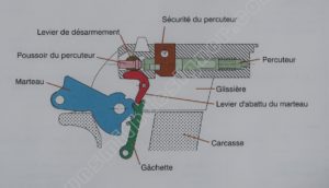
Drawing of the first version of the P38 (sources: Le P38 by Michel Malherbe).
It was this second version (with an exposed hammer), named Heeres Pistole, that was adopted in 1938 under the designation P38. Manufacturing began in November 1939.
I will not delve further into the history of this firearm, as I have neither the skills of a historian nor the desire to do so. This brief overview serves to situate the period and context in which this firearm fits. Indeed, it allows us to place it on what I call the timeline—the common thread of technical advancements in automatic pistols.
The firearm presented in this article is not a military version produced during World War II, but rather a more “modern” version featuring an aluminum frame.
The right side
The left side
For historical details, many books exist on the subject, for example:
Book cover: Le P38 by Michel Malherbe.
General Specifications:
- Width of the firearm: 36.7 mm;
- Height of the firearm: 136 mm;
- Length of the firearm: 245 mm;
- Weight of the firearm with an empty magazine: 790 grams;
- Caliber: 9 mm.
Front left side
Front right side
Below are links that will take you to various user manuals:
- Walther Manual 1
- Walther Manual 2
- Walther Manual 3
- French Military Manual
On the “Download” page of the website, there are various documents available for consultation. New additions are made regularly… so feel free to check that page from time to time.
Description of the Firearm by Assembly
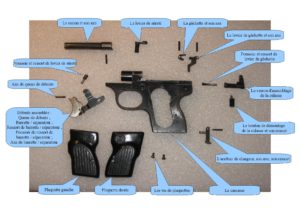
Exploded view of the firearm
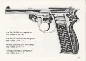
Cutaway view of the firearm
Parts list
The Frame Assembly
The assembled frame brings together 32 parts.
The frame assembly, along with the magazine
The frame without its grip panels, left side
The frame without its grip panels, right side
The stripped frame is made of anodized aluminum. A few steel inserts have been installed into the frame, notably the lanyard loop, the housing for the slide stop and sear spring, and the trigger bar spring housing.
Stripped frame, right side
Stripped frame, left side
It is a complex part when compared to its French “competitor” of the era: the MAS 35 A.
Bottom left of the frame
Top of the frame
Takedown lever housing
Bottom right of the frame.
The frame underwent a simplification compared to the original version. Here, it concerns the choice of material: aluminum. It is a very pleasant material to machine that leaves a fine surface finish without wearing down tooling and allows for higher machining speeds. The advantage is twofold, as the overall weight of the firearm is also reduced.
Rear of the stripped frame
Hammer housing
Front of the frame
Top of the frame
The trigger is made of steel. It includes its return spring, which is held in place by a hollow pin. Having a self-contained sub-assembly is very convenient, as it facilitates disassembly and reassembly. The trigger pin also serves as the slide stop pin.
The trigger return spring
The assembled trigger
The slide stop pin doubles as the trigger pin
The single-action trigger pull weight is: 1.930 kg.
The double-action trigger pull weight is: 4.9 kg.
The figures above are given as an indication, as the values vary depending on the angle of the gauge relative to the trigger.
The sear is an investment-cast part. Its shapes are complex. Choosing to machine this part from solid stock would tie up significant resources, requiring numerous operations, fixtures, and likely specialized tooling.
The sear.
The sear, showing the single-action cocking notch.
The sear.
The photos below show the part mounted on the frame. Notice that the part sits on the outer sides of the frame rather than inside. The trigger return spring acts on the sear via the trigger bar.
The sear mounted on the frame.
Left side of the mounted sear.
The hammer resembles a revolver hammer operating in double action. Naturally, this is no surprise, as it draws inspiration from revolver hammers of that era that had proven their reliability over time. As such, double action is achieved via a small double-action strut (fly) that pivots on a pin and is driven by a spring.
Right face of the hammer.
Left face of the hammer.
A single-action cocking notch is also present on the hammer. It is used when firing in single action. After cocking the hammer manually or following a shot, the hammer remains caught on this notch.
The three parts mounted on the hammer pin.
Rear of the hammer.
The hammer cocked in its housing.
The hammer pin also serves as the pivot pin for the firing pin safety lever (to the right of the hammer) and the decocking lever (to the left of the hammer).
The trigger bar and its spring are made of steel. This part acts as the intermediary between the trigger and the sear.
Inward-facing side of the trigger bar.
The trigger bar housing.
Outward-facing side of the trigger bar.
When the slide is not fully closed, the trigger bar is disconnected from the sear. In other words, the hammer cannot be released from its cocked notch if the trigger is pulled while the slide is out of battery.
The projection on the trigger bar has entered its recess in the slide; firing can occur.
The trigger bar mounted on the firearm.
The trigger bar mounted on the firearm.
The hammer strut transmits the force of the mainspring to the hammer. It also acts as a guide rod for the mainspring. Its lower end fits into the magazine catch.
The mainspring acts on two parts. Upward, it exerts force on the hammer strut (and thus on the hammer); downward, an equal force is applied to the magazine catch.
On certain firearms, the mainspring is under such heavy tension that great care must be taken during disassembly. This is not the case on this version of the P38—quite the opposite.
The mainspring, hammer strut, and magazine catch.
The three parts mounted on the frame.
The magazine catch is made of formed sheet steel. It is a very well-crafted component.
One can find articles criticizing this heel-release style rather than a thumb-operated push button. The argument most often put forward is the need to shift one’s grip on the firearm, thus losing time during a reload. Through this section, I wish to pay tribute to an elderly gentleman I had the opportunity to meet in the past. A retired customs officer, he had served in the colonies, notably in Indochina. I remember one of his anecdotes: while issued a Colt .45, he once accidentally dropped his magazine and only realized it at the worst possible moment. After that misadventure, he acquired a P38 and was delighted with it.
The installed magazine catch.
The magazine catch alone.
The slide stop is made of steel. It appears to be a two-piece assembly. The pivot pin seems to be separately fabricated and staked onto the body. The body itself is an investment-cast part.
The slide stop.
The slide stop.
The slide stop and sear spring serves two functions. Each leg acts on a different part. The left leg acts on the slide stop, while the other side acts on the sear pin and, to a lesser extent, the sear itself.
Slide stop spring.
The installed slide stop.
Recoil recovery is handled by 2 recoil springs housed within the frame. Guide rods keep the springs in place inside their channels.
Dimensions of the recoil springs:
- Outer diameter: 5.4 mm;
- Wire diameter: 0.6 mm;
- Spring lengths: 103.7 mm and 104.2 mm.
The recoil springs mounted on the frame.
Recoil springs and guide rods.
The ejector is stamped from thin sheet steel. Notably, it sits loosely in its housing, moving back and forth inside the magazine well. This is surprising at first glance. Once the magazine is inserted, the ejector returns to its proper position. No device forces it to stay rearward, which is rather unusual.
The ejector mounted on the frame.
The ejector
The grip panels are made of black plastic. Reinforcing ribs are molded into the inside of both panels to strengthen the parts.
Inside of the grip panels.
The grip panels.
The takedown lever is mounted on the frame. It controls the forward travel of the slide. Once rotated, the lever allows the barrel/slide assembly to slide off forward. Prior to this, the magazine must be removed.
This part serves as the forward stop for the barrel. Its rearward stop is the frame (specifically, the front of the magazine well).
The assembled takedown lever.
The takedown lever alone.
To operate the lever, the slide must be pulled back a few millimeters to align a notch on the left side of the slide with the takedown lever.
The takedown lever housing.
The Slide Assembly
The assembled slide is made of steel; it is a short, open-top design since the barrel is not enclosed by it.
The P38 pistol slide comprises 15 parts.
The stripped slide fits within an envelope measuring: 139.5 mm x 30.1 mm (width) x 27.8 mm (height). It is made of steel.
The stripped slide.
Underside of the stripped slide.
The stripped slide.
The locking block recesses are machined into each side. A notch at the top of the breech face houses the loaded chamber indicator.
The breech face.
Underside of the slide.
The firing pin and its retaining pin are machined from a steel cylinder.
A small “center punch mark” is located at the rear; it serves as an alignment guide during firing pin reassembly. To reassemble it properly, the punch mark must be oriented toward the rear sight. By positioning this mark toward the top of the firearm, the two notches at the rear of the firing pin align with their corresponding parts (specifically, a right-angled notch on the right side of the firing pin aligns with the firing pin safety, while on the left, the rounded notch aligns with the firing pin retaining pin).
The firing pin.
Top alignment mark on the firing pin.
The firing pin.
The retaining pin features a shoulder. Below, the firing pin can be seen installed inside the slide.
The firing pin in its channel.
The firing pin retaining pin.
The firing pin spring serves two purposes. The first is to push the firing pin rearward; the second is to retain the loaded chamber indicator in its housing.
The firing pin spring is mounted at the front of the firing pin. It is uncommon to see a firing pin spring shaped like this.
The firing pin spring.
The installed firing pin spring.
The extractor, its spring, and its plunger are conventional. It is worth noting that the loaded chamber indicator is a separate component, which adds a certain degree of complexity. Indeed, on some automatic pistols, the extractor doubles as a loaded chamber indicator. Such a solution would have avoided machining the top of the slide.
The extractor
The extractor plunger and its spring.
The extractor.
The safety lever houses a spring and a plunger. When this lever is flipped down, the hammer drops safely. It acts as a manual safety by blocking the firing pin’s path and as a decocking lever by releasing the sear via the decocking lever.
The safety lever housing on the slide.
The safety lever housing.
The loaded chamber indicator is a drop-forged part. It is pushed forward by a coil spring. When a cartridge is chambered, the loaded chamber indicator protrudes from the rear of the slide, between the rear sight and the top of the hammer.
As mentioned earlier, this design introduces a certain level of complexity—not because of the part itself, but due to its channel in the slide, the addition of the top cover plate, and the shape of the firing pin spring.
The loaded chamber indicator and its spring.
The loaded chamber indicator in its housing.
The firing pin safety is a mechanism designed to prevent any accidental discharge. Indeed, as long as the shooter does not pull the trigger, firing cannot occur because this part physically blocks the path of the firing pin.
The firing pin safety.
The rear sight is a small steel block. As we will see later, it is non-adjustable. It is held in place by the slide top cover.
The rear sight.
Underside of the rear sight.
The rear sight.
The slide top cover is a piece of stamped sheet metal that covers the machined channel created for the loaded chamber indicator.
The Barrel Assembly
The assembled barrel
Right side of the barrel, locking block in the raised position.
Left side of the barrel.
Locking block in the raised position.
The stripped barrel is made of steel and fits within an envelope measuring: 125.5 mm x 25.3 mm (width) x 28 mm (height).
The locking block lug on the barrel.
Rear of the barrel.
The locking block is removable. It is a solid steel piece. It locks the slide to the barrel during a specific portion of travel. By pivoting up and down, two lugs on the locking block engage into recesses in the slide, thereby locking the barrel to the slide.
Underside of the locking block.
Top of the locking block.
The locking block.
The locking block spring is a small V-shaped leaf spring that retains the locking block on the barrel.
The locking block spring.
View of the barrel in its housing.
The locking block plunger is carried by the barrel. It forces the locking block to drop down (in other words, it forces unlocking) when the barrel recoils—that is, during firing or when pulling the slide back manually.
The locking block plunger in its housing.
The locking block plunger.
The base of a chambered cartridge protrudes by 2.2 mm.
The Sights
The rear sight is made of steel. It is removable but non-adjustable. It is held in place by the sheet metal cover over the firing pin channel: the slide top cover.
Profile of the rear sight notch.
The rear sight mounted on the slide.
The front sight is removable and is dovetailed onto the barrel. Consequently, it is possible to make use of this fit to adjust windage (to the right or left), as well as elevation by replacing it with a shorter or taller blade. This requires having a set of front sights on hand.
The front sight on the barrel.
Profile of the front sight.
The Magazine
The magazine is conventional, made of folded sheet steel. The edges of the sheet are spot-welded together along the front left corner of the magazine.
It consists of:
- A magazine body;
- A follower (the part in contact with the cartridges);
- A spring;
- A floorplate lock;
- A floorplate.
Stripped magazine, right side.
Disassembled magazine.
Stripped magazine, left side.
The magazine capacity is 8 rounds. The number of remaining rounds can be checked through the witness holes drilled on each side.
Magazine loaded with one cartridge.
The Locking Principle
In the Colt-Browning system, locking lugs are machined onto the barrel, and locking recesses into the slide. The rear of the barrel tilts up and down. In the lowered position, the barrel and slide are unlocked. In the raised position, the barrel is locked to the slide.
Barrel in the forward position, locking block in the raised position.
On the P38, the barrel and the locking block are two separate parts. The locking block is carried by the barrel. The barrel moves straight back and forth, while the locking block pivots up and down. The total fore-and-aft travel of the barrel is 7 mm, divided into two phases:
- Free recoil / locked travel: 4 mm;
- Locking/unlocking travel: 3 mm.
Between these two phases—at what we will call the intermediate position—the locking block plunger contacts the frame. As the barrel continues its rearward travel, the plunger forces the locking block downward, initiating unlocking.
Barrel in the intermediate position.
At the end of its rearward travel, the barrel comes to rest against the frame. The locking block is in its lowered position, and the slide is completely unlocked. While the barrel stops its rearward movement, the slide, having stored kinetic energy, continues rearward on its own.
Barrel in the rearward position.
The rear of the barrel contacts the front of the frame.
Barrel in the rearward position, locking block in the lowered position.
We have seen how the locking block plunger pushes the locking block down. But how does it return to its raised position? When the recoil springs decompress, the slide moves forward again. When the slide strikes the rear face of the barrel (which is sitting in its rearward position), the slide pushes the barrel forward. As the barrel advances, the locking block plunger exerts progressively less downward force on the locking block. Locking takes place over 3 mm, followed by the remaining 4 mm of locked travel.
What forces the locking block back up into its raised position is the lug on the underside of the locking block. Looking at the photo of the inside of the frame (below), we can see that a portion of the anodizing has worn away, exposing bare metal. This is caused by the friction of the underside of the locking block rubbing at this exact spot. It is this bearing surface and the angled ramp preceding it that cam the locking block back up into its locked position.
Bearing surface on the underside of the barrel.
Bearing surface of the locking block on the frame.
Conclusion
I took immense pleasure in disassembling this firearm. It is simple, well-engineered, and well-manufactured. It field-strips very easily without requiring any specialized tools.
The version presented here is an evolved variant compared to the wartime military model. If the evolution is minimal, it is because the firearm’s design was remarkably well thought out and sufficiently ahead of its time to stand the test of decades without needing major additions. The sole evolution concerns the frame material: aluminum.
From the very beginning, the design was intended to be simpler than the P08, yet it is by no means simplistic. The P38 is a sophisticated firearm that retains certain aesthetic cues from the P08.
It is interesting to note that the magazine release on the P08 is positioned under the shooter’s thumb. On the P38, however, the magazine catch is located at the heel of the grip (more secure, albeit slower for reloading). In my view, this reflects a deliberate choice not to repeat a past mistake. Motorcycle officers of the Gendarmerie or police know a thing or two about this—it is not uncommon for them to lose their magazines on the road due to thumb push-button releases meant to save reload time. See also the anecdote mentioned earlier in the article.
Around the same period, the Browning Hi-Power (GP35) appeared (a high-capacity, or intermediate-capacity, pistol). One minor regret is that there was never a “crossbreed” between the two designs—namely, a high-capacity P38. That fusion would come much later in the form of the Beretta 92, which is another story we will cover soon.
In a previous article, The Master Plan of Technical Advancements in French Service Pistols, we examined French handguns. It is clear that the French firearms industry of that era lagged behind its German and Belgian neighbors. It took two years in Germany to modify a prototype (featuring a brand-new locking system) and put it into production. In France, it took 18 years to field the MAC 35 A and its Colt-style locking system—18 years for a firearm that was already obsolete upon release! That is deplorable! It was not merely a delay, but a lack of vision, or even incompetence, on the part of French design bureaus and decision-makers.
Both the GP35 and the P38 originated from private civilian companies—hence the importance of maintaining a dedicated domestic industrial base well-versed in modern manufacturing techniques and products.