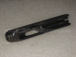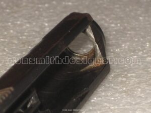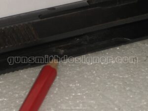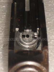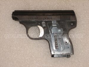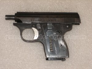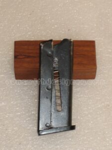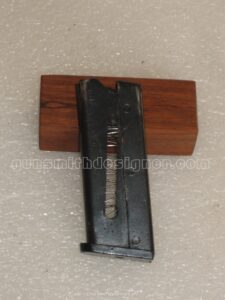
The Manufrance Buffalo mechanism

I would like to introduce or reintroduce you to a very interesting mechanical design. It was produced in various calibers and even in the “Eureka” and “Mitraille” configurations, which fired two and three shots simultaneously, respectively. This action is that of the Manufrance Buffalo rifle. We will study it through various catalog excerpts and a cutaway educational model.

Engraving from the Manufrance catalog showing the company's premises.

 The Buffalo action

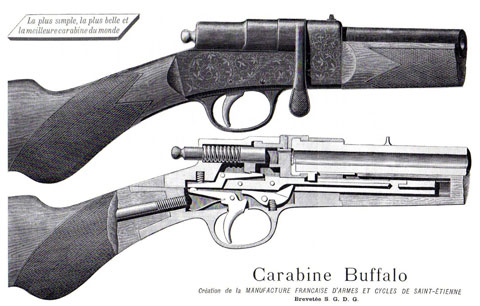
Standard and sectional views of the right side of the Manufrance Buffalo mechanism.

Assembling a firearm around a Buffalo action results in a highly elegant piece. When looking for modern firearms of identical caliber or similar type, one mostly encounters what are known as “garden guns” (carabines de jardin). However, the character and finish of these modern equivalents have absolutely nothing to do with the design, charm, and refinement of the Buffalo. Manuarm or Gaucher rifles are modern equivalents that are more economical but also cruder.
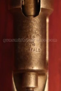
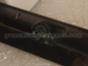
View of the receiver marking showing the weapon's model name.

Centered around a solid steel receiver, the Buffalo action is composed of few parts, but they are well-dimensioned. It seems highly unlikely for a part to break. If it were to happen, I would lean more towards a broken spring, though not the firing pin spring, as it is massive. Although this mechanism appears simple, the shapes of its components are far from it and require numerous machining, fitting, and finishing steps.
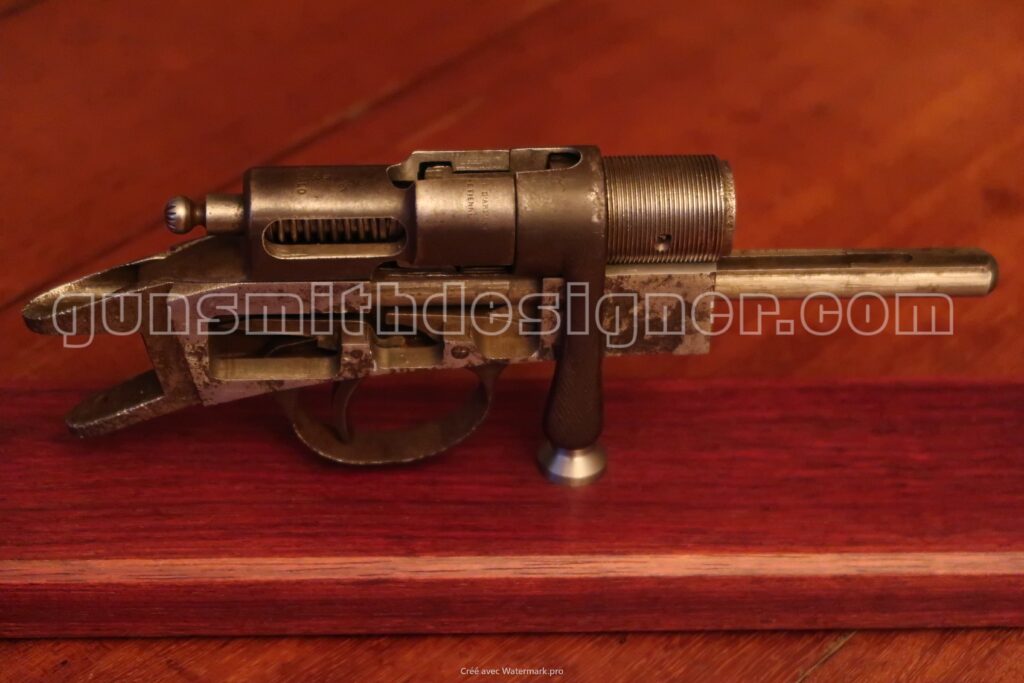
Cross-sectional view of the right side of the Buffalo mechanism.

The shapes of the bolt assembly’s main component, for example, are no longer produced on modern firearms. Nowadays, manufacturers primarily seek geometric profiles that are easy to manufacture. In a way, this is an aberration since modern CNC machines can work wonders. It appears that our predecessors preferred elegance over maximum profitability. Perhaps also, a certain mechanical complexity was the norm and did not prevent them from being profitable… something to ponder.
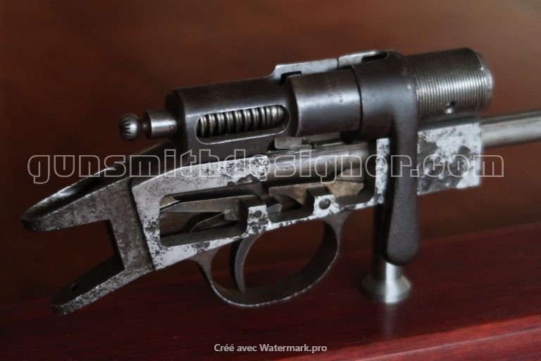
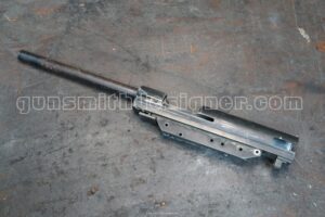
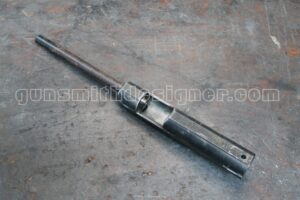
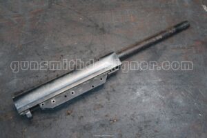
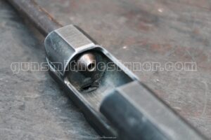
The Buffalo rifle is a bolt-action firearm where locking occurs directly on the barrel. The barrel carries the locking lugs, and the breechblock/shutter carries their recesses—generally, it is the other way around. The locking lugs are massive; each measures 15 mm high, 5.8 mm wide, and 1.3 mm thick. Locking or opening is achieved by a quarter-turn turn, manipulating the cocking handle. This single part combines several functions, such as: locking/closure, cocking the firing pin, and a firing pin safety that prevents firing if the cocking handle is not in the lowered position.

The barrel is threaded into the receiver with a 28 x 100 thread. Two small set screws hold it in place on each side of the barrel. Various versions and profiles were manufactured. Because the locking lugs are located on the barrel, if one wished to remove the barrel, after removing the two small set screws on each side, it would have to be threaded inward so that it exits through the rear of the receiver.
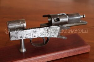
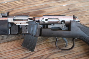
Thanks to an inclined plane that forces the firing pin backward, the user cocks the firing pin when operating the bolt handle. The firing pin remains cocked against the sear when the bolt assembly is open. The sear is carried by the bolt assembly.
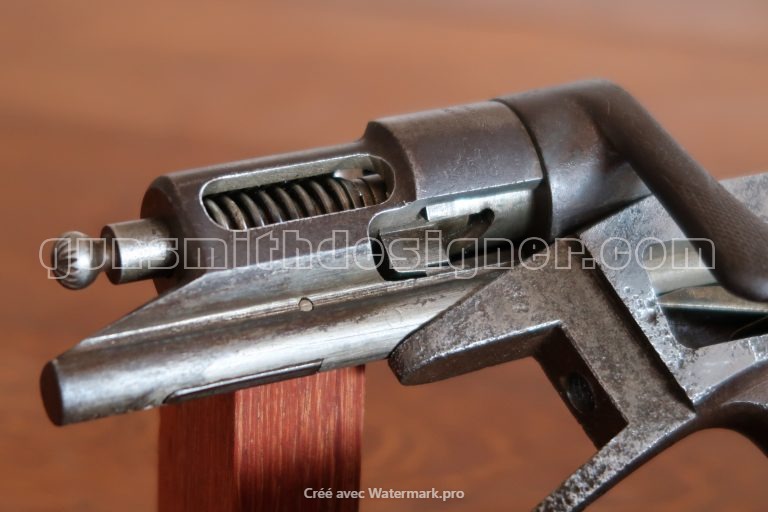
Cross-sectional view of the Buffalo with the action open.

Upon closing the breech block or bolt assembly, the sear resets directly above the trigger blade. Once loading and closure are complete, pulling the trigger allows the shooter to fire.
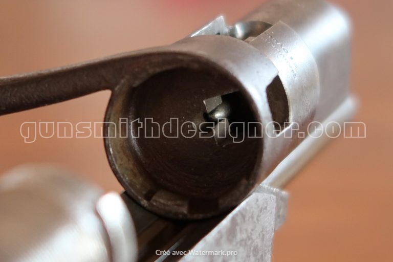
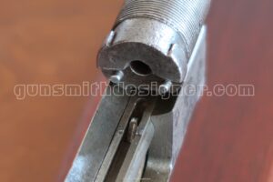
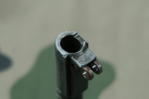
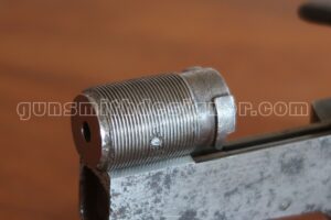
View of the breech face and the firing pin tip.

The telescopic design of the bolt reduces the overall footprint of the mechanism while providing real access to the chamber, which is crucial since this is a manually loaded firearm. Few modern firearms allow such extensive access. With the bolt closed, the mechanism measures 148 mm in length (excluding the portion that inserts into the stock forend).
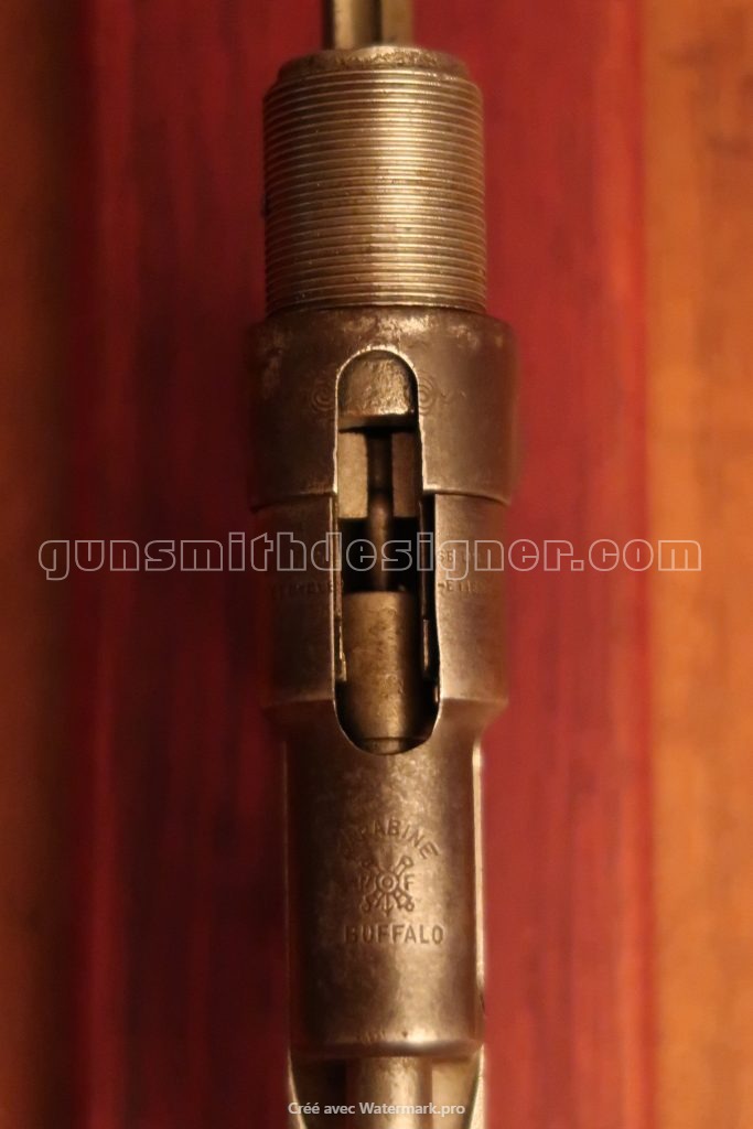
Top view with the action closed, detailed view of the firing pin travel.

The parts are all flawlessly manufactured, with no machining marks visible on their surfaces. Only time and corrosion have weathered some of them.

The stock is screwed onto the receiver. The screw is accessible underneath the buttplate. If you replace this screw, pay close attention to its length, as it can interfere with the mechanism (specifically, it can come into contact with the trigger blade).

Disassembling the bolt assembly

User disassembly of the Buffalo rifle mechanism consists of separating the bolt assembly from the receiver, followed by the shutter and the firing pin.

  • Unlock and open the bolt ;
  • Push the trigger blade forward ;
  • Pull the bolt assembly backward to separate it from the receiver ;
  • Retrieve the extractor, which will slip out of its housing following the previous step ;
  • Force (reasonably) the opening of the cocking handle past its stop ;
  • Slide the breechblock/shutter out toward the front ;
  • Press the sear to release the firing pin (do not stand directly in front of it) using a wooden block for support.

Disassembling the remaining fixed parts requires proper tools.

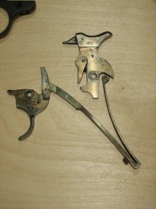
If you own one of this weapon, it would probably be a good thing to disassemble the set of trigger / disassembly lever as it is quite possible that these parts and their housing have not known cleaning for many years. To do this, you must move two pins over the trigger. For the same reason, continue with the disassembly of the trigger. Thoroughly clean the assembly (parts, springs and housings) then reassemble everything clean after a light greasing. If you do not feel able to do it, or if you are not able to do it properly (which in my eyes is the same), have it done by a professional. Do not consider that it is money lost, since it is a weapon that can only take value, it is an investment.
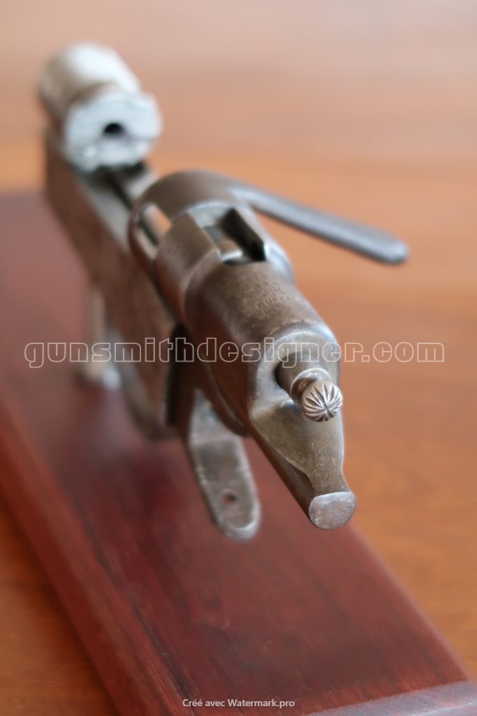
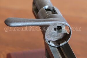
Rear view of the bolt.

Special barrels

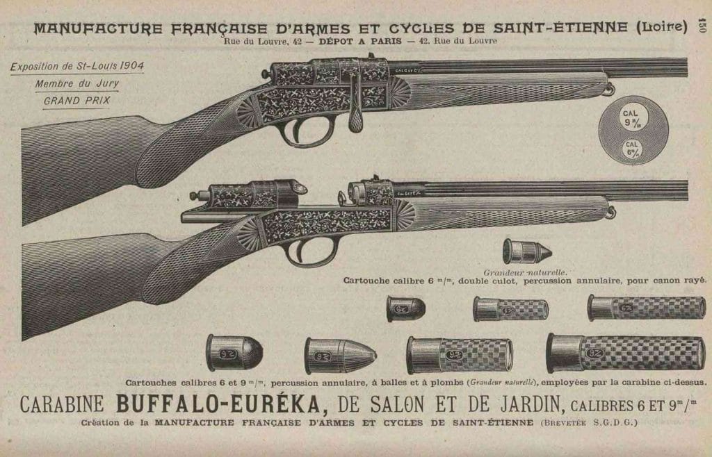
As mentioned in the introduction, the action was adapted into special versions: the Buffalo Mitraille and Buffalo Eureka.
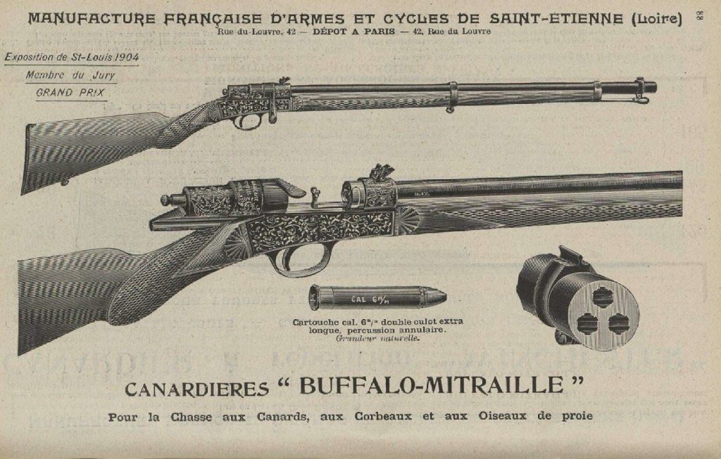
Engraving of the Buffalo Mitraille rifle

Buffalo Mitraille

Engraving of the Buffalo Eureka rifle

Buffalo Eureka

Who would amuse themselves today by drilling two or three bores into a single steel bar? Probably not many people. The reason is that this process combines several major difficulties, namely :

  • Drilling over a length of 45 to 60 cm without the drill bit straying from its path ;
  • Rifling the barrel bore when it is not located in the center of the bar. It is more difficult to find a reference surface in this scenario ;
  • The target results must be grouped at a reference distance and must not disperse excessively if one moves away from that reference distance.

It is easy to drill a single straight through-hole in a metal bar. If you want to achieve a concentric barrel, you simply turn the outside of the bar on a metal lathe to match the outside using the inside as a reference (turning between centers). However, here, it is far more complex. As if the Eureka rifle were not enough with its two bores in a single bar, Manufrance engineers designed the Buffalo Mitraille, which features 3 bores.

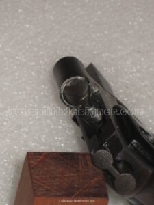
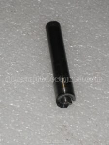
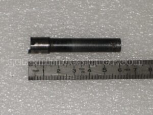
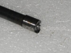
 Since these two or three rounds fire simultaneously, it implies a specialized firing pin. Since you need to extract the three fired cases together, a two- or three-slot extractor is also required, making it a more complex component as well.

Conclusion

Manufrance holds a very special place in my heart for more than one reason. This place is reinforced when studying the mechanisms coming from this company in depth. Over time, one notices a distinct continuity: the streamlined nature of Manufrance firearm actions. Beneath an apparent simplicity lie terribly well-designed, robust mechanisms containing few parts and utilizing high-quality materials. One might think simplicity is easy, but it is not. Employing fewer parts means hiding components with multiple functions and complex shapes. We can include in this common thread: the Le Français pistol, the Buffalo rifle, the Simplex shotgun, the Robust shotgun, the Idéal shotgun…

These are now firearms from another era, when products from France and old Europe had to be exported to every corner of the globe (North Africa, Sub-Saharan Africa, Indochine, South America, Oceania, Europe…) and withstand all kinds of harsh environments to be passed down from generation to generation.

I began this profession, after obtaining my degree, by working in a Parisian gunsmith shop. Just a stone’s throw from it, which still exists today, is a home for Malian workers. The latter, looking for the “marfa ciré” (spelling probably incorrect, translation: good gun), bought single-shot Baikal shotguns to send back to Mali. However, the shotgun that held genuine value in their eyes was the Simplex. This was around the years 1994–2000: long after Manufrance had closed its doors.
Posted in All articles, Handguns, Rifles | Leave a comment

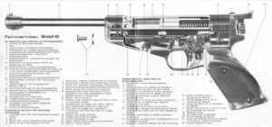
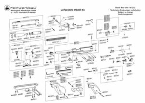
FEIN 65, dismounting of the barrel.

Some information is difficult to find because it is poorly documented. Either it is of no interest, or no one has thought to organize this information and make it available to the general public. Let me present one of these rare pieces of information: how is the barrel of a Fein 65 (air pistol) mounted onto the receiver ?

Having a mediocre-conditioned specimen of this weapon on hand, I took the opportunity to answer this question.

Barrel Disassembly

Before trying a specific disassembly method, one must define what the expected barrel mounting method is. The possible mounting methods include :
  • Threaded/Screwed ;
  • Press-fitted ;
  • Pinned ;
  • Glued/bonded ;
  • Welded (highly unlikely here) ;
  • Several of the solutions mentioned above ;
  • …

As for me, having no certainty, I hesitated between several likely choices (press-fitting or threading). I considered two options:
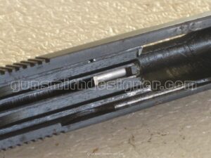
  • Placing the barrel under a press and attempting to extract it forward. If the barrel is threaded into the receiver, I risk damaging the parts by stripping the threads ;
  • Machining the receiver to relieve all or part of the tension around the barrel, thereby checking whether or not the barrel is threaded into the receiver. This is a destructive method.

I decided to test the first option. If it didn’t work, I would fall back on the second one. To do this :

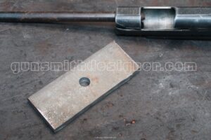
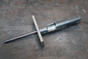
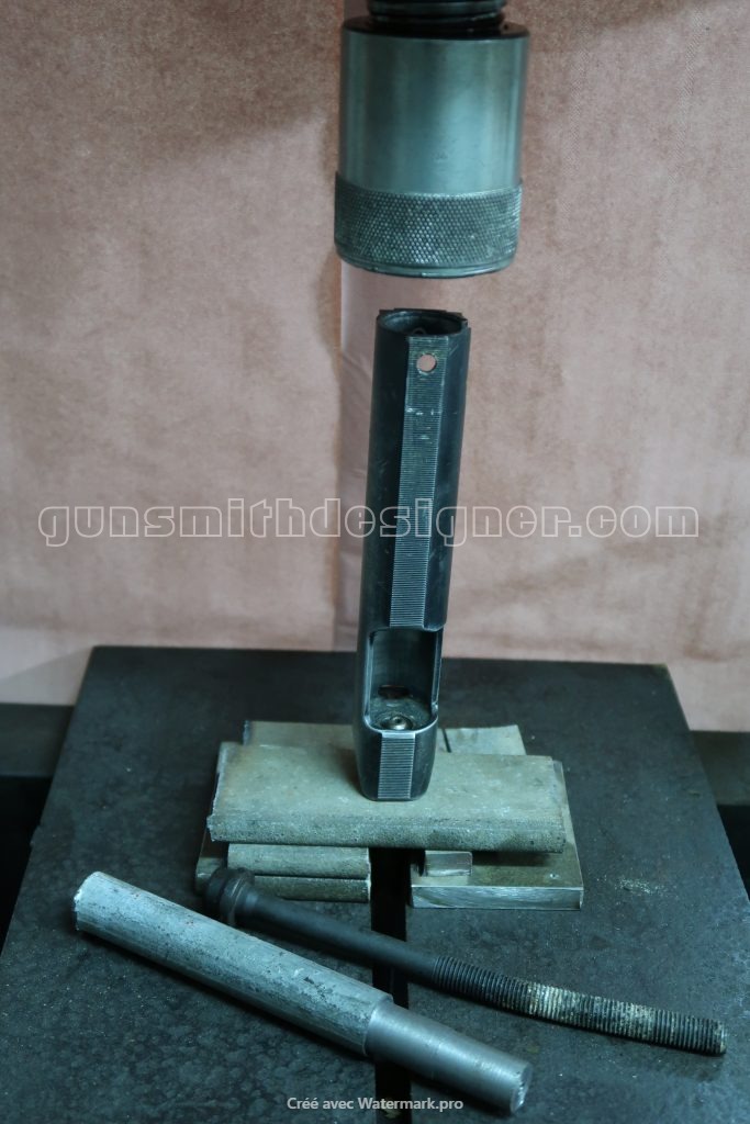
  • I drilled a steel plate approximately 10 mm thick with a 13 mm diameter drill bit. This will serve as a stop for the receiver ;
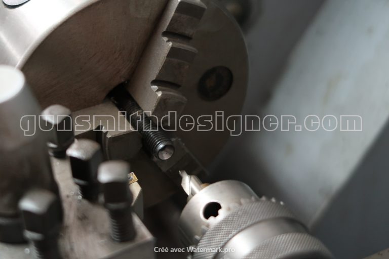
  • Creating the barrel housing on the barrel pusher (since the barrel is tapered) ;

Machining of the barrel pusher.

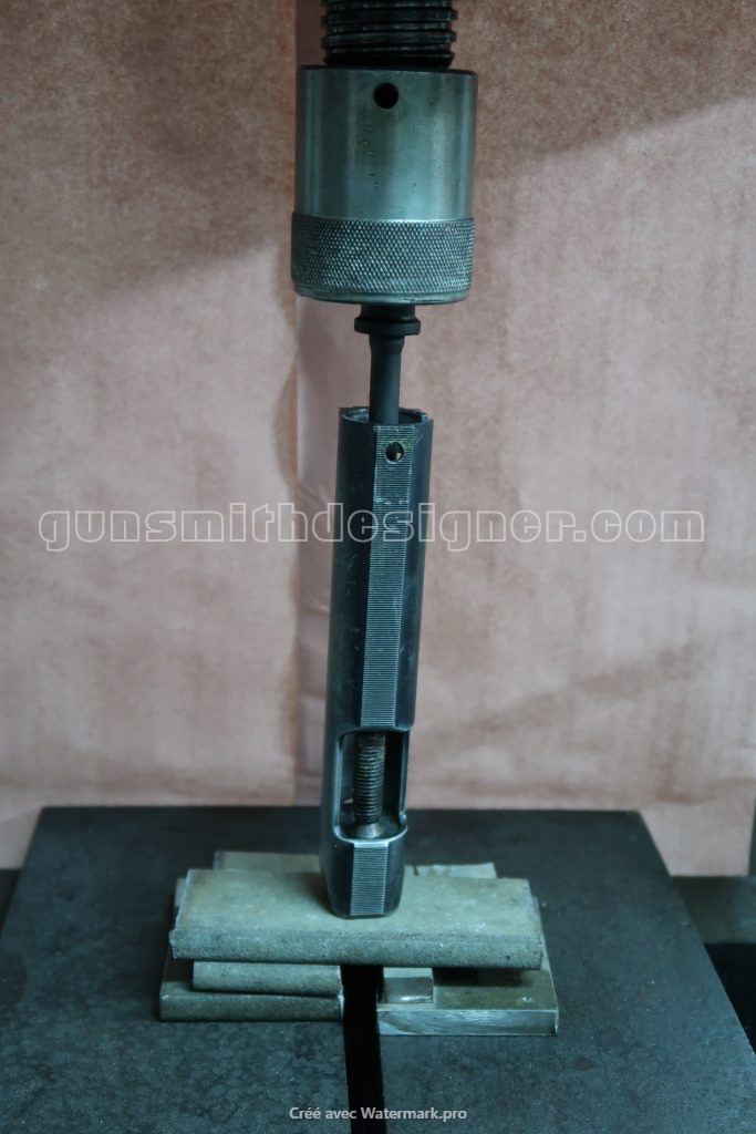
  • Setting up the assembly on the press ;

The frame mounted on the press.

  • Following the first pressurization, it turns out that the pusher is not suitable. The first pusher used was a car cylinder head bolt. The latter bent under the pressure of the press (see photo below). The second pusher used is a solid steel bar with a diameter of 20 mm.
The pusher bent under the load of the press.
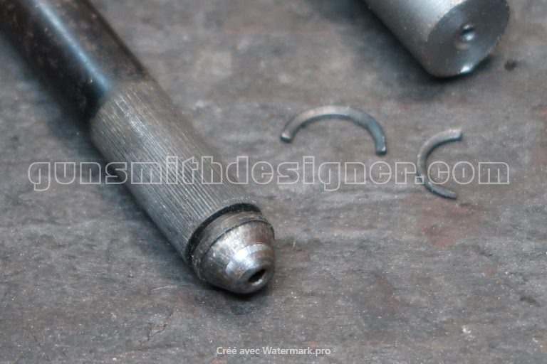
  • With this new pusher, the force of the press was fully applied to the barrel. After a loud snap, the barrel came out of its housing. The snapping sound was caused by the breaking of two steel circlips.

View of the removed barrel of the Fein 65.

    • Looking at these circlips, it would seem that the barrel is mounted by pushing it from the inside of the receiver. Therefore, I should have removed it by pushing it towards the inside of the receiver. This would not have broken the circlips.
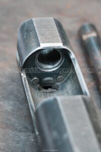
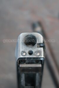
    • The barrel housing on the receiver is clean. The diameter of the barrel housing in the receiver is 13 mm. The breaking of the two circlips (which act as a barrel stop on the receiver) did not damage the barrel housing.

Possible next steps

What could be the follow-up to this article? It would be quite interesting :

  • To cut a thread on the receiver and fit various barrels. We could then test a Fein 65 in .22 (5.5 mm) or .25 (6.35 mm) caliber, for example. Given that the barrel housing on the receiver is 13 mm, the chosen thread could be M14 x 100 ;
  • To see if the volume of compressed air produced by the original mechanism is sufficient to propel a larger and heavier projectile than the original one ?
  • To measure the velocity of the different calibers for various barrel lengths ?
  • To fit longer barrels to test if the air volume is sufficient ;
  • If the trials prove successful, it would then be possible to adapt the Fein 65 into an air rifle version…, or even a take-down air rifle ;
  • To consider this removal method to replace a worn barrel and thus refurbish shooting club Fein 65s ;
  • To dismantle a second Fein 65, but this time by pushing the barrel towards the inside of the receiver to compare the two methods ;
  • …
Posted in All articles, Handguns, Manufacturing techniques | Leave a comment

The Sterling pistol 302 in 22 Lr

In this new article, we will discover the Sterling pistol chambered in .22 LR. I wanted to introduce you to this small pistol because it offers a useful comparison with the Bernardelli Baby pistol, which was described in a previous article. This will be an opportunity to look at a similar pocket pistol equivalent, but in a different caliber and with distinct design choices.

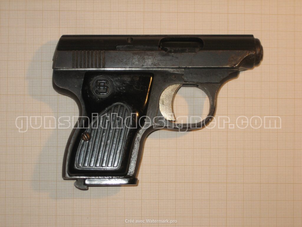
View of the right face of Sterling 302.

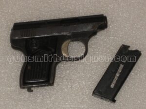
Sterling 302 pistol.

The Sterling firm did not exist for very long, and the company’s strategic choices were probably the cause. This can be seen through the firearms they marketed, notably a compact version of the High Standard pistol. It is hard to believe that it actually sold. The 302 pistol seems to represent a genuine effort to market a true compact pistol, rather than just a shortened version of an already existing model. You can find more information on the following page: weaponsman.com.

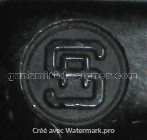
Logo of Sterling

Specifications of the Sterling 302

  • Overall length : 140 mm ;
  • Overall height : 90.5 mm (with magazine), 88 mm (without magazine) ;
  • Overall thickness : 25.5 mm ;
  • Weight : 421 grams (with an empty magazine), 442 grams with a magazine loaded with 6 rounds ;
  • Barrel length: 59.5 mm ;
  • Caliber: 22 Lr ;
  • Capacity : 6 rounds in the magazine + 1 in the chamber ;
  • Action type : single action ;
  • Safety lever on the left side of the frame ;
  • The grip is good, the weapon sits relatively high on the hand for its small size ;
  • The weapon is entirely made of steel (except the grip panels) ;
  • Number of parts: 43.

Field Stripping the Sterling 302 (User Disassembly)

Field stripping this firearm does not require any special tools. The various steps to accomplish this task are detailed below :

⚠️ Point the firearm in a safe direction before any handling.

  • Remove the magazine from the weapon ;
  • Verify that the chamber is empty ;
  • Press the button that unlocks the slide assembly lever ;

View of the rear of the Sterling 302 frame.

  • The assembly button pops out of its housing ;

The unlocked assembly lever.

  • Once unlocked, the slide lifts out through the top ;

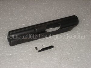
The Sterling 302 pistol slide during disassembly.

  • Field stripping is now complete ;

The disassembled Sterling 302 pistol

Sub-assemblies of Sterling 302

The pistol is composed of the following sub-assemblies :

  • The slide sub-assembly ;
  • The frame/barrel sub-assembly ;
  • The magazine sub-assembly.

The slide sub-assembly

This sub-assembly is composed of 8 parts :

  • The slide ;
  • The extractor ;
  • The extractor spring ;
  • The extractor pin ;
  • The recoil spring ;
  • The firing pin ;
  • The firing pin spring ;
  • The firing pin spring guide.

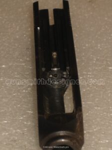
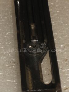
The slide is made of steel. It appears to be produced by investment casting (micro-fusion) and then machined. Casting and machining marks are visible. The slide alone is rather heavy and massive. The weight of this part is 136 grams. The dimensions of the raw block envelope are: length = 119 mm, thickness = 20.4 mm, height = 20.1 mm.

The distance between the barrel axis and the top of the frame is 6 mm. This is significant because comparing this dimension across several firearms can give us an idea of the overall volume, the height of the sight line over the hand, the barrel diameter, and insights into the choices made by the designers…

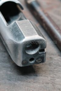
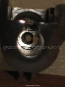
The diameter of the breech face (the recess for the cartridge case rim in the slide) is approximately 8 mm (not easy to measure precisely), with a depth of 1 mm. The breech face is highly critical. Indeed, you will notice the presence of two holes: one for the firing pin tip and the second for the ejector.

The relationship between the firing pin channel and the ejector channel.

The slide travel (the same with or without the recoil spring) is 30.6 mm, whereas a live round measures about 25 mm.

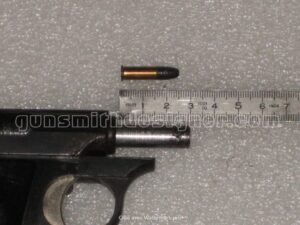
The muzzle extending from the slide in relation to the size of a .22 LR cartridge.

Gunsmith disassembly for the slide consists of removing the extractor. A pin holds it in place; drive it out, and you will gain access to the extractor and its spring.

The recoil spring measures 73 mm. The wire diameter is 0.9 mm. The outer diameter of the spring is 11.6 mm. The reader can count the number of spring coils themselves on the photo below.

The Sterling 302 recoil spring.

Although the slide retains some machining marks, the firing pin is perfectly machined. Its diameter is 7 mm. The tip of the firing pin has a diameter of 1.5 mm for a length of 2.7 mm.

With an almost identical mechanism, one can compare the firing pin of the Sterling pistol (rimfire) and that of the Bernardelli Baby pistol (centerfire) to contrast the designers’ choices. Two small bevels are present on the firing pin tip; they are there to provide better penetration into the cartridge case rim during ignition.

The firing pin rests back on its sear notch after the slide travels 26.7 mm backward.

Ejection occurs via the extension of the firing pin spring guide rod. A hole runs through the firing pin to allow this extension to pass through so it can fulfill its role as an ejector.

The frame / barrel sub-assembly

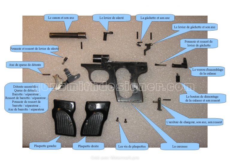
Exploded view of Sterling 302.

This sub-assembly is composed of 29 parts. Here is the list :

  • The frame ;
  • The Canon ;
  • The barrel pin ;
  • The safety lever ;
  • The sear ;
  • The sear pin ;
  • The sear lever;
  • The sear lever pin ;
  • The sear lever plunger ;
  • The sear lever spring ;
  • The slide assembly lock ;
  • The slide disassembly button ;
  • The disassembly button spring ;
  • The magazine catch ;
  • The magazine catch pin ;
  • The magazine catch spring ;
  • The safety lever spring plunger ;
  • The safety lever spring ;
  • The trigger ;
  • The forward trigger stop (pin not disassembled) ;
  • The trigger pin ;
  • The trigger bar / disconnector ;
  • The trigger bar disconnector pin ;
  • The trigger bar disconnector spring plunger ;
  • The trigger bar disconnector spring ;
  • The right grip panel ;
  • The left grip panel ;
  • 2 grip screws.

Left side view of the bare frame, Sterling 302.

The frame is a massive part; it weighs 179 grams (bare component). Its dimensions are: height: 79 mm, thickness: 13.5 mm, length: 106.5 mm.

View of the frame without the barrel.

The trigger mechanism includes the following parts :

The parts of sear mechanism.

As seen above, the force applied by the shooter’s finger pressure on the trigger is transmitted via the trigger bar/disconnector to the sear lever. The latter pivots around its axis and drives the sear, causing it to drop and release the firing pin. The springs provide the necessary force for the parts to return to their original positions.

The magazine sub-assembly

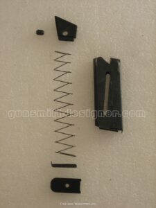
The magazine consists of 6 parts :

  • The magazine body ;
  • The magazine folower ;
  • The magazine folower spring ;
  • The magazine follower stop pin ;
  • The magazine floorplate lock ;
  • The magazine floorplate.

The magazine capacity is 6 rounds.

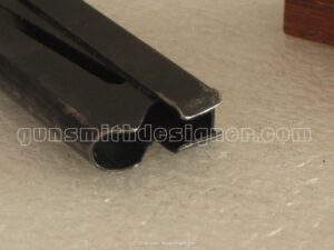
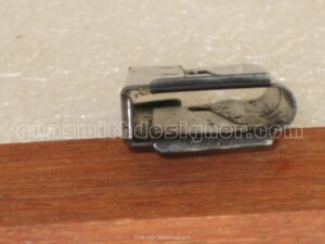
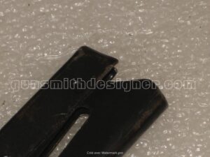
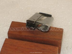
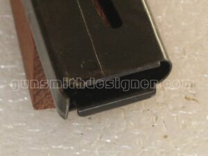
Instead of utilizing a single piece of sheet metal, the manufacturer used two pieces which were then spot-welded together with three points on each side. The two metal sheets used do not have the same thickness (0.8 mm for the rear sheet forming the magazine lips, 0.6 mm for the front sheet).

The magazine slides perfectly into its well.

Live Fire Testing the Sterling 302

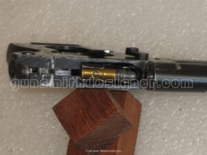
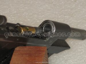
The first shooting session did not go very well. It was impossible for me to fire a complete magazine without a malfunction. The recurring issue was cartridge feeding/chambering. With every shot, extraction and ejection were fine, but the next round failed to chamber properly.

To feed the next round, I had to close the slide by pushing it forward by hand. When feeding manually (directly into the chamber, without the slide or magazine), the cartridges had difficulty fully seating into the chamber.

The second session took place after polishing the chamber. Now, the ammunition chambers smoothly, and there are no further issues. I was able to complete a shooting session without any malfunctions.

Conclusion

Simple in design and execution, the Sterling 302 pistol is a relatively crude and robust weapon. The number of parts is limited; there is no superfluous detail.

The Sterling 302 pistol could have benefited from greater care during the chamber finishing stage (at least for the specific model I had in hand). This is, after all, the most critical aspect—why buy a defense weapon if it jams with every round fired?

Even though it is a low-cost firearm, one must keep in mind the sheer number of manufacturing steps required to yield a finished frame, slide, and all the other components. Add to this initial calculation the time spent on hand-fitting and finishing, and the profit margins must not have been very significant.

It could be interesting to see an aluminum frame variation to lighten the overall weight of the weapon. Given that the slide is massive, it is possible it might create an imbalance in the firearm, which remains to be seen.

With a significantly larger volume than the Bernardelli Baby despite its smaller caliber, the Sterling 302 pistol also sits higher on the hand. On the other hand, the grip ergonomics are more pleasant on the 302, as there is more room available.

Posted in All articles | 3 Comments